
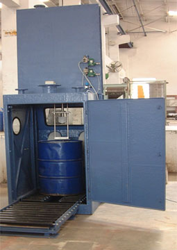
Liquid Drum Evacuation System
- The system consists of an MS – PU painted enclosure. The enclosure will have door at the back & glass panels on the front & the sides. The front side of the enclosure will have a sight glass & a pair of hand gloves. The enclosure will have a drum-locating fixture having split idler rollers & an arrangement for rotating the drums. The enclosure will have a suction port for connection to the plant scrubber system.
The booth will have an idler roller conveyor at the loading end with a pneumatic cylinder connected with drum clamping fixture for lifting the drum from the pallet to the loading conveyor.
- Drum Evacuation System consists of the following Specification:
- FRP coated MS PU painted Cabin with door, door sensor, sight glass & hand gloves.
- Drum tilting fixture with foot switch operated pneumatic bellow & split idler rollers.
- Rodless pneumatic cylinder assembly with FLP solenoid valve, suction pipe, obstruction sensor, drip scoop & bung hole guide plate.
- Loading idler roller conveyor with filled drum lifting pneumatic cylinder, drum-clamping fixture, cross trolley & supporting structure.
- Control panel housing the PLC to be located in the flameproof area.
The booth will have an idler roller conveyor at the loading end with a pneumatic cylinder connected with drum clamping fixture for lifting the drum from the pallet to the loading conveyor.
- FRP coated MS PU painted Cabin with door, door sensor, sight glass & hand gloves.
- Drum tilting fixture with foot switch operated pneumatic bellow & split idler rollers.
- Rodless pneumatic cylinder assembly with FLP solenoid valve, suction pipe, obstruction sensor, drip scoop & bung hole guide plate.
- Loading idler roller conveyor with filled drum lifting pneumatic cylinder, drum-clamping fixture, cross trolley & supporting structure.
- Control panel housing the PLC to be located in the flameproof area.