VACUNAIR ENGINEERING CO P LTD.
Featured Products
Highest quality standards are achieved through the implementations of latest technology, decades of experience and everlasting moral values , which have helped us to retain our customers as well as multiply them.
Welcome to VACUNAIR ENGINEERING CO P LTD.
Centrifugal Air Blower
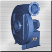
Series HF AEROMATIC High Efficiency Centrifugal Air Blowers / Fans are a new concept in Fan Engineering. Each type 14 to 40 has different specific speed for best efficiency. Each type has various sizes selected from basic log series of preferred numbers. This has made it possible to select the best type and size for a given speed, capacity and pressure. Selection of SWSI / DWDI / Multistage is based on specific speed for a suitable type for best efficiency.
Special Features:
» Series of high efficiency fans are a new concept in fan Engineering. Each type 14 to 40 has different specific speed for best efficiency
» Can handle Air / Hot flow gases / Corrosive gases / Dust / Fiber / Powder material
» Unique bearing pedestal design for longer bearing life / easy alignment
» Impeller is backward curved / backward inclined / radial / forward curved selected to suit the application. Impeller is dynamically balanced
» Single / Multi stage design
Side Channel Blower
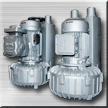
General Information:
» In the chambers set in the periphery the impeller, air is accelerated due to centrifugal force created as the impeller turns and is thrown into the next chamber and is again similarly accelerated, thus continuously increasing compression as the impeller turns until it reaches the outlet port.
Features:
» Non pulsating continuous air flow.
» Compact & light weight
» No metal to metal contact, Oil free air
» Rugged construction, maintenance free
» Low noise level
» Additional filter system (optional).
» Construction cast aluminum alloy
Axial Flow Fans
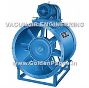
Axial Flow Fans are available in
Capacity: Up to 3,00,000 M3/hr
Pressure: Up to 100 mm of WG.
» To achieve high efficiency, fans have a defined hub ratio of 75 to 25 for given capacity, pressure and speed
» Impeller blades are adjustable type and can rest at designed angle to suit the system resistance
» Fan can run in parallel to suit capacity and in series for higher pressure
» Impeller is made of aerofoil profile from cast aluminum alloys
» Bifurcated type fans are available for handling corrosive gases
» High efficiency can be achieved due to wide selection of sizes, hub ratio, number of blades and pitch angle
Variable Inlet Vane Damper
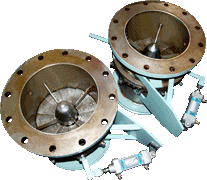
Working Principle / General Information:
» VIV Dampers are designed with mechanical principle of adjustment.
» Inlet guide vanes are synchronously adjustable in the same angular position by a connecting element.
» Adjustment can be made either automatically via an adjusting element from pulse generator by hand.
Special Features:
» Energy Savings with fans utilizing variable inlet vanes.
» VIV Dampers are often used for capacity modulation. They give accurate modulation and power savings over other styles of dampers at reduced air flow.
» When an inlet vane is partially closed, each blade directs the air into the wheel in the direction of rotation and so the air is prespun. This brings about a reduction in the Capacity, Static Pressure and BHP. The amount of BHP savings at reduced capacity is determined by the type of system and type of fan-vane combination.
» For every inlet vane position there is different Capacity V/s Static curve and Capacity V/s Brake Horsepower (BHP) curve generated by the fan.
» VIV Dampers are designed with mechanical principle of adjustment.
» Inlet Guide vanes are Sychronously adjustable in the same angular postion by a connecting element.
» Adjustment can be made either automatically via an adjusting element from pulse generator or by hand.
Trim Handling System And Shredder Cum Conveying Blower
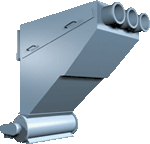
General Information:
» Trim Handling device is engineered to suck continous trims of paper, plastic, laminate and the like material. It consists of high efficiency fan for motive air, well designed ventury and discharge cone.
» High velocity air from motive fan induces sufficient suction at suction nozzles to suck trims. Trims can be conveyed to waste collector, boiling or repulping tanks.
Features:
» All parts are specially designed for specific installation to consume optimum low power.
» Specially designed seperator that can be placed very near to the main equipment. This reduces discharge pipe resistance and the power required can be reduced to half or less. This seperator can be moved to the place of disposal.
Pneumatic Conveying System
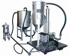
General Information:
» Pneumatic Conveying Systems can be tailor made to suit exact requirements of any bulk material to be conveyed. The system is enviro-friendly.
» Can offer suction conveying, low pressure conveying, high pressure conveying depending upon the typical nature of the product, conveying rate and the distances
» Can design and offer a system which can be fully manual, semiautomatic and fully automatic.
Features:
» Can handle materials like flour of all types, dextrose, clay powder, coal dust, soda ash, plastic pellets, grits, powders, Soya meal/beans, catalysts of all types & sizes, LDPE / HDPE pellets, wood chips, groundnut, paper, plastic & laminate
» Specialists in catalysts loading / unloading for refineries and fertilizer plants.
Flux Supply And Recovery Unit
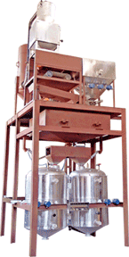
PLC based automatic Flux Supply & Recovery Unit:
» Flux supply & recovery unit is working based on vacuum and high pressure pneumatic conveying system.
» This system is divided in three assemblies.
1. Flux recovery and conditioning assembly
The flux recovery is based on vacuum conveying system. the additional flux supplied to the welding point will be recovered with use of vacuum conveying and will be stored at recycle flux storage vessel. the dusty air will pass through the reverse pulse jet type filter cleaning arrangement and clean air will be exhaust of to the atmosphere.
The recycle flux will be reconditioned with the help of 3 stage flux conditioning unit. the first stage will remove the large slugs particles collected during the suction. the second stage will remove the magnetic particles from the collected flux. the third and final stage will remove the dust particles from the collected flux.
The collected flux will be mixed with new flux through flux management system. we had provided two types of flux management system, one is one-by-one timer control system and other-one is online flow control mixing system.
In one-by-one timer control system, the new flux and recycled flux will be mixed with the help of set-up timers which can be set in the hmi panel. this mixing ratio can be varied from 20% to 50% new flux to the recycle flux with the use of time control system. in this system, first we will allow to collect recycle flux, then after new flux. such cycle can be repeated depends upon requirements.
2. Flux supply assembly
This mixture of the flux will be transferred to the set of flux supply tanks. these tanks are provided with periphery type surface heater to maintain the temperature of flux to be supplied for the welding purpose. this flux will be transfer through pressure conveying system.
Our Vision
* To embrace new technologies and methods. * To give unsurpassed products and services to the clients. * To constantly look for improvement and changes.


